// Thermal-Fluids
Fuel-Cooled Oil Cooler Heat Exchanger Design
Designed and analyzed an aircraft FCOC heat exchanger (Boeing 757-class) using ε-NTU on a finned shell-and-tube geometry in 2024-T6 aluminum.
Overview
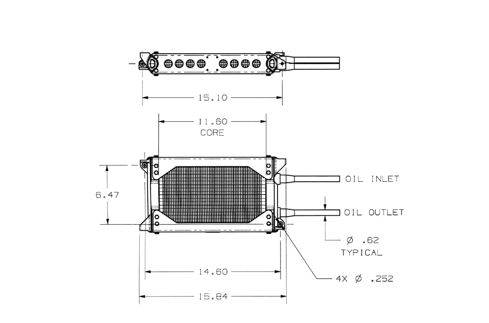
Three-person team project for MAE 3187 (Heat Transfer): design and analyze a fuel-cooled oil cooler (FCOC) for the Boeing 757, where engine fuel acts as the heat sink for hot lubrication oil before combustion. Operating points used: oil in 87 °C → out 74 °C at 0.302 kg/s, fuel in 38 °C at ~0.694 kg/s, with 2024-T6 aluminum tubes and fins in a finned shell-and-tube geometry.
Approach
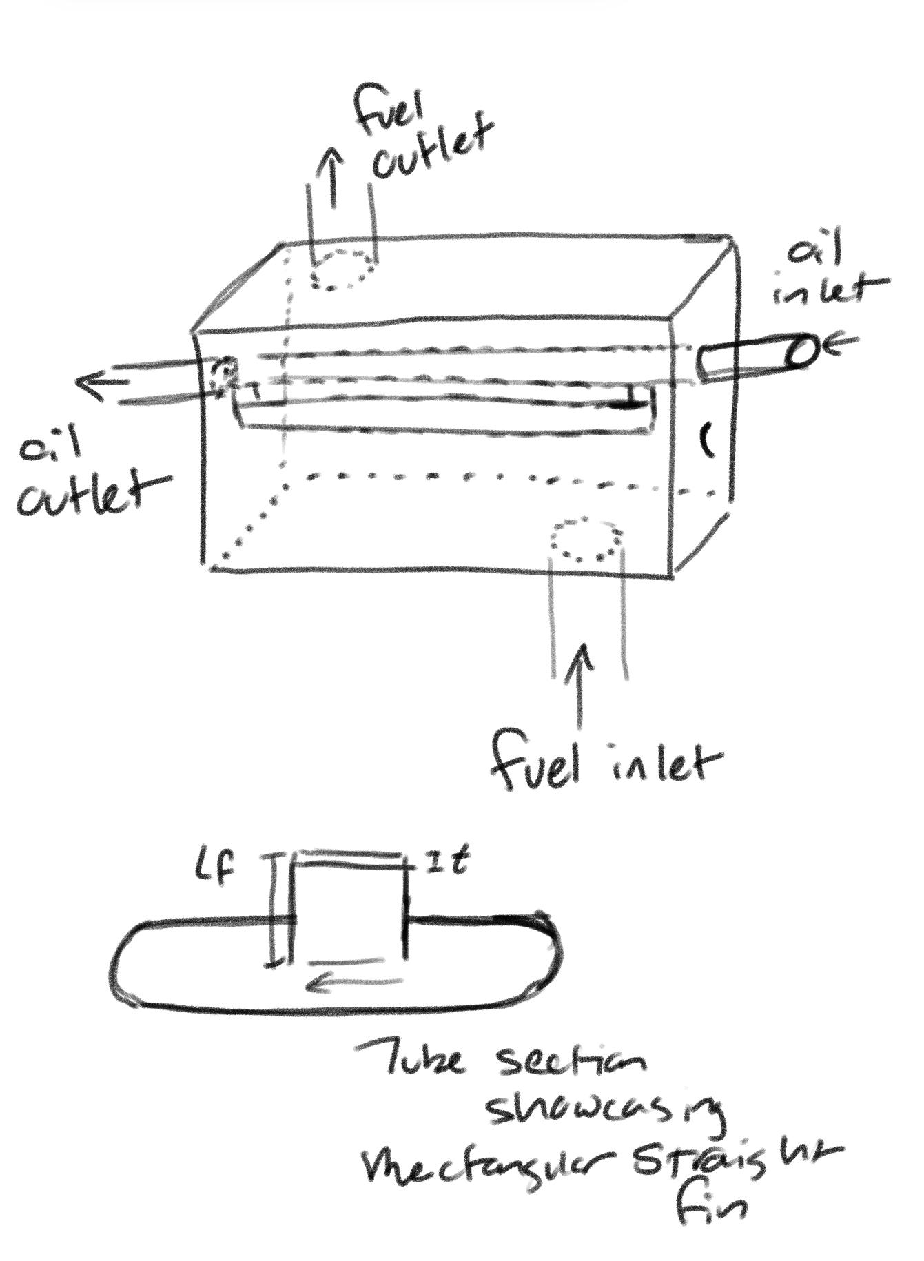
We modeled the FCOC as a 2-pass, finned shell-and-tube exchanger and applied the ε-NTU method (Incropera Eq. 11.30a) to size it. Internal oil-side convection used the Dittus–Boelter correlation: Re_oil ≈ 1.23 × 10⁵, Pr_oil ≈ 0.0040, Nu ≈ 29.7, giving h_oil ≈ 287 W/m²K. The fuel side ran fully turbulent (Re_fuel ≈ 1.02 × 10⁶). Fin and prime-surface areas, fin efficiency, overall surface efficiency, and total thermal resistance were computed, then iterated on geometry (tube count, passes, fin count, fin length) to hit the target heat duty within reasonable pressure drop.
Figures
My contribution
I led the oil-side thermal analysis (Re/Pr/Nu chain through to h_oil), contributed to the ε-NTU sizing, wrote and ran the Python sizing scripts, and produced the heat-exchanger schematic and outlet-temperature predictions used in the final report.
Result
An optimized FCOC profile (4 tubes, 2 passes, 120 fins, 0.007 m fin length) that improved overall thermal resistance to ≈ 0.061 K/W and predicted oil and fuel outlet temperatures of ≈ 49.5 °C and ≈ 56.4 °C respectively — meeting the cooling duty with realistic 757-class geometry.
Next project
Golf Ball Mechanism →
Mechanical Subsystems